Creep resistance is a crucial property when it comes to parallel groove clamps, which are widely used in electrical power systems for connecting conductors. As a supplier of parallel groove clamps, understanding and ensuring the high creep resistance of our products is of utmost importance.

What is Creep in the Context of Parallel Groove Clamps?
Creep refers to the slow and progressive deformation of a material under a constant load over time. In the case of parallel groove clamps, they are subjected to mechanical forces and electrical currents during normal operation. The mechanical forces come from the tightening of the clamp onto the conductors and the external forces such as wind, vibration, and thermal expansion and contraction of the conductors. Electrical currents can also cause heating, which may further affect the material properties of the clamp.
When a parallel groove clamp experiences creep, it can lead to a loosening of the connection between the clamp and the conductors. This loosening can result in increased electrical resistance at the connection point. Higher resistance means more heat is generated, which can accelerate the aging of the materials, damage the conductors, and even pose a safety hazard such as electrical fires or short - circuits.
Factors Affecting the Creep Resistance of Parallel Groove Clamps
Material Selection
The choice of material for parallel groove clamps is a primary factor influencing creep resistance. High - quality metals with good mechanical and thermal properties are typically used. For example, aluminum alloys are commonly employed due to their lightweight, good electrical conductivity, and relatively high strength. Aluminum alloys with appropriate alloying elements can have improved creep resistance. Copper is another excellent choice, known for its high electrical conductivity and better creep resistance compared to some other metals. It can maintain its shape and connection integrity under long - term loading more effectively.
Manufacturing Process
The manufacturing process of parallel groove clamps also plays a significant role. Precision machining and proper heat treatment can enhance the internal structure of the material, improving its creep resistance. For instance, heat treatment can relieve internal stresses in the material, which reduces the likelihood of creep deformation. Additionally, accurate forming and sizing during manufacturing ensure that the clamp fits tightly onto the conductors, minimizing the initial mechanical stress concentration points that could lead to creep.
Design Features
The design of the parallel groove clamp affects its creep resistance. A well - designed clamp should distribute the mechanical load evenly across the contact area with the conductors. This can be achieved through features such as a proper groove shape and a uniform clamping force. For example, some clamps are designed with multiple bolts or screws to ensure a more balanced pressure distribution. A clamp with a wider contact area can also reduce the stress per unit area, thereby improving creep resistance.
Testing and Assurance of Creep Resistance
As a parallel groove clamp supplier, we conduct rigorous testing to ensure the creep resistance of our products. We use advanced testing equipment to simulate real - world operating conditions. For example, we can apply a constant mechanical load to the clamp for an extended period while monitoring the deformation. Electrical tests are also carried out to measure the change in electrical resistance over time, as an increase in resistance can be an indication of creep - induced loosening.
We follow international standards and industry best practices in our testing procedures. This ensures that our parallel groove clamps meet or exceed the requirements of our customers. By providing products with high creep resistance, we can offer long - term reliability and safety in electrical power systems.
Related Products and Their Significance
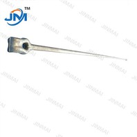
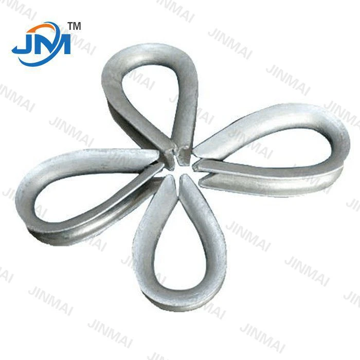
In addition to parallel groove clamps, our product range includes other electrical power fittings such as FTTH Fitting Splint Wire Hook, Stay Rod Thimbal, and Power Supply Fittings. These products work in conjunction with parallel groove clamps to ensure the proper functioning of electrical power systems.
FTTH Fitting Splint Wire Hooks are used in fiber - to - the - home (FTTH) networks. They help in securing and organizing the wires, ensuring a stable connection. Stay Rod Thimbals are important for providing mechanical support to stay rods, which are used to anchor poles in the ground. Power Supply Fittings are essential for delivering electrical power safely and efficiently from the source to the end - users.
Why Choose Our Parallel Groove Clamps?
Our parallel groove clamps stand out in the market due to their high creep resistance. We source the best materials and use state - of - the - art manufacturing processes to produce clamps that can withstand the test of time. Our products are designed to provide a reliable and long - lasting connection between conductors, reducing the risk of electrical failures and maintenance costs.
We also offer customized solutions to meet the specific needs of our customers. Whether it is a small - scale project or a large - scale power grid, we can provide the right parallel groove clamps with the appropriate specifications. Our technical support team is always ready to assist customers in choosing the best products for their applications.
Contact Us for Procurement
If you are in need of high - quality parallel groove clamps or any of our other electrical power fittings, we invite you to contact us for procurement. Our products are designed to meet the highest standards of quality and performance. We are committed to providing excellent customer service and ensuring that your electrical power systems operate smoothly and safely.
References
- "Handbook of Electrical Power System Design and Analysis" by Turan Gonen
- "Materials Science and Engineering: An Introduction" by William D. Callister Jr. and David G. Rethwisch
- Industry standards related to electrical power fittings and their performance requirements.